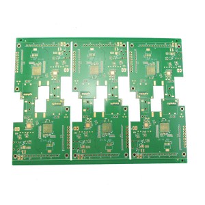
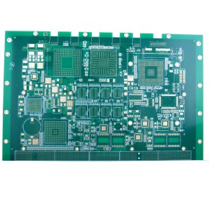
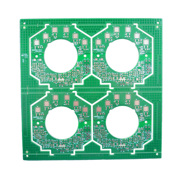
6 layer circuit board for industrial sensing & control
Product Details
| Layers | 6 layers |
| Board thickness | 1.60MM |
| Material | Shengyi S1000-2(TG≥170℃) FR-4 |
| Copper thickness | 1 OZ(35um) |
| Surface Finish | ENIG Au Thickness 0.05um; Ni Thickness 3um |
| Min Hole(mm) | 0.203mm |
| Min Line Width(mm) | 0.15mm |
| Min Line Space(mm) | 0.18mm |
| Solder Mask | Green |
| Legend Color | White |
| Mechanical processing | V-scoring, CNC Milling(routing) |
| Packing | Anti-static bag |
| E-test | Flying probe or Fixture |
| Acceptance standard | IPC-A-600H Class 2 |
| Application | Industrial control |
Multilayer
In this section, we would like to supply you with basic details about the structural options, tolerances, materials, and layout guidelines for multilayer boards. This should make your life easier as a developer and help to design your printed circuit boards so that they are optimized for manufacturing at lowest cost.
General details
| Standard | Special** | |
| Maximum circuit size | 508mm X 610mm (20″ X 24″) | --- |
| Number of layers | to 28 layers | On request |
| Pressed thickness | 0.4 mm – 4.0mm | On request |
PCB Materials
As a supplier of various PCB technologies, volumes, lead time options, we have a selection of standard materials with which a large bandwidth of the variety of types of PCB can be covered and which are always available in house.
Requirements for other or for special materials can also be met in most cases, but, depending upon the exact requirements, up to about 10 working days may be needed to procure the material.
Do get in touch with us and discuss your needs with one of our sales or CAM team.
Standard materials held in stock:
| Components | Thickness | Tolerance | Weave type |
| Internal layers | 0,05mm | +/-10% | 106 |
| Internal layers | 0.10mm | +/-10% | 2116 |
| Internal layers | 0,13mm | +/-10% | 1504 |
| Internal layers | 0,15mm | +/-10% | 1501 |
| Internal layers | 0.20mm | +/-10% | 7628 |
| Internal layers | 0,25mm | +/-10% | 2 x 1504 |
| Internal layers | 0.30mm | +/-10% | 2 x 1501 |
| Internal layers | 0.36mm | +/-10% | 2 x 7628 |
| Internal layers | 0,41mm | +/-10% | 2 x 7628 |
| Internal layers | 0,51mm | +/-10% | 3 x 7628/2116 |
| Internal layers | 0,61mm | +/-10% | 3 x 7628 |
| Internal layers | 0.71mm | +/-10% | 4 x 7628 |
| Internal layers | 0,80mm | +/-10% | 4 x 7628/1080 |
| Internal layers | 1,0mm | +/-10% | 5 x7628/2116 |
| Internal layers | 1,2mm | +/-10% | 6 x7628/2116 |
| Internal layers | 1,55mm | +/-10% | 8 x7628 |
| Prepregs | 0.058mm* | Depends on layout | 106 |
| Prepregs | 0.084mm* | Depends on layout | 1080 |
| Prepregs | 0.112mm* | Depends on layout | 2116 |
| Prepregs | 0.205mm* | Depends on layout | 7628 |
Cu thickness for internal layers: Standard - 18µm and 35 µm,
on request 70 µm, 105µm and 140µm
Material type: FR4
Tg: approx. 150°C, 170°C, 180°C
εr at 1 MHz: ≤5,4 (typical: 4,7) More available on request
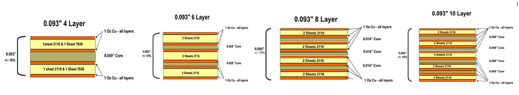
Stack up
PCB stack-up is an important factor in determining the EMC performance of a product. A good stack-up can be very effective in reducing radiation from the loops on the PCB, as well as the cables attached to the board.
Four factors are important with respect to board stack-up considerations:
1. The number of layers,
2. The number and types of planes (power and/or ground) used,
3. The ordering or sequence of the layers, and
4. The spacing between the layers.
Usually not much consideration is given except as to the number of layers. In many cases the other three factors are of equal importance. In deciding on the number of layers, the following should be considered:
1. The number of signals to be routed and cost,
2. Frequency
3. Will the product have to meet Class A or Class B emission requirements?
Often only the first item is considered. In reality all the items are of critical importance and should be considered equally. If an optimum design is to be achieved in the minimum amount of time and at the lowest cost, the last item can be especially important and should not be ignored.
The above paragraph should not be construed to mean that you can’t do a good EMC design on a four- or six-layer board, because you can. It only indicates that all the objectives cannot be met simultaneously and some compromise will be necessary. Since all the desired EMC objectives can be met with an eight-layer board, there is no reason for using more than eight layers other than to accommodate additional signal routing layers.
The standard pooling thickness for multilayer PCBs is 1.55mm. Here are some examples of multilayer PCB stack up.
Metal Core PCB
A Metal Core Printed Circuit Board (MCPCB), or a thermal PCB, is a type of PCB that has a metal material as its base for the heat spreader portion of the board. The purpose of the core of an MCPCB is to redirect heat away from critical board components and to less crucial areas such as the metal heatsink backing or metallic core. Base metals in the MCPCB are used as an alternative to FR4 or CEM3 boards.
Metal Core PCB Materials and Thickness
The metal core of the thermal PCB can be aluminum (aluminum core PCB), copper (copper core PCB or a heavy copper PCB) or a mixture of special alloys. The most common is an aluminum core PCB.
The thickness of metal cores in PCB base plates is typically 30 mil - 125 mil, but thicker and thinner plates are possible.
MCPCB copper foil thickness can be 1 - 10 oz.
Advantages of MCPCB
MCPCBs can be advantageous to use for their ability to integrate a dielectric polymer layer with a high thermal conductivity for a lower thermal resistance.
Metal core PCBs transfer heat 8 to 9 times faster than FR4 PCBs. MCPCB laminates dissipate heat, keeping heat generating components cooler which results in increased performance and life.